
DESCRIPTION
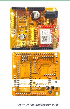
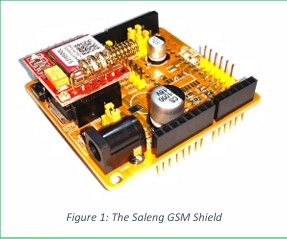
The Saleng GSM shield adds SMS, GPRS and data call
capabilities to your Saleng Uno or Arduino projects. The
board greatly simplifies implementation with its
Arduino “shield” form factor and integrated supporting
circuits. All that is required is an Arduino or any
microcontroller with a UART, the Saleng GSM shield and
5-12Vdc/2A source of power. No complicated wiring.

- FEATURES
- Powered by SIM800L GSM module.
- detachable/ replaceable core SIM800L
- Onboard 3A LDO and Level Shifter circuit
- Arduino Shield form factor with Arduino Nano
- pin header slots
- Wide external input voltage: 5V ~ 12V
- Onboard DC Jack with slots for Terminal Block
- option
- Integrated antenna and micro SIM card slot
- Jumper selection for power source, UART pins
- and Power Enable method
-
- RI and TXD LED indicators
This shield is a culmination of several years of
experience working with GSM modules, in particular,
the SIMxxx series. The shield is powered by the popular
SIM800L GSM module and comes with the necessary
power circuit, logic level conversion and SIM card slot. It
also comes with an integrated helical spring antenna.
There are mini jumpers onboard for other hardware
options.
The shield is compatible with any microcontroller or
computer with a Serial Port (UART). The serial port,
audio in and out, and other signal lines from the
SIM800L are exposed via pin headers on the top layer.
With an Arduino however, connection is even faster
with the stackable pin headers. The Arduino UNO,
Mega, Leonardo, Zero and other boards and clones of
the same form factor are compatible with the shield
connectors. There are also pads that allows a user to


Recommended Power Supply Current = 2A for
heavy communications. May be lower current
for simpler applications
HARDWARE OVERVIEW
POWER REQUIREMENTS
The SIM800L core module alone has a peak current of 2
Amperes during communications. This may be brief but
is significant if communications is continuous. The
whole shield draws a current below 200mA when the
SIM800L is idle. With these we recommend a power
supply rated at least 2A with a voltage of 5V up to 12V.
However, because of the shield’s design, using a 1A
power supply may also work for applications with less
active communications.
JUMPER OPTIONS
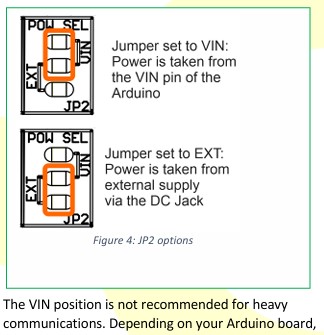
Power Source Selection: Jumper JP2
The 3-pin header labeled POW SEL allows the user to
choose where the input power for the shield will be
sourced from. It may either come from the power
source connected to the DC Jack (“EXT”) or from the
VIN pin of the Arduino (“VIN”).
- APPLICATIONS
- There are several applications involving GSM
- communications with computers. Listed below are
- some applications
- Remote monitoring and notification
- SMS/Data Call/GPRS remote control
- Machine-to-Machine communications
- GPRS modem
- Internet-of-Things (IOT)


there is a 1A power diode between the DC Jack of the
Arduino and the VIN pin. The shield may draw up to 2A
during communications, therefore, if the shield is used
extensively and continuously, it is recommended to use
an external power supply instead and set the jumper to
the EXT position. You may also simply split the power
source and connect the Arduino’s DC plug and the
Saleng GSM Shield’s DC plug in parallel so long as the
common power supply used meets the power
requirements of both boards (6-12V). Keep the jumper
in the EXT position if this option is desired.
For communications with wider time intervals, the VIN
position simplifies power wiring as you only need to
connect your power supply at the Arduino’s DC Jack.
The power is then propagated to the shield via the Vin
pin of the Arduino. This means only the DC jack of the
Arduino needs to be inserted with power.
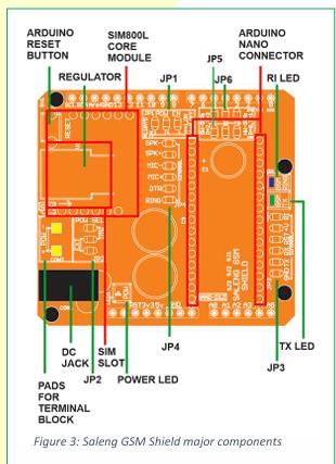
UART Pin Selection: Jumper JP5 & JP6
There are 2 columns representing the TX and RX pins of
the SIM800L. Using the 2 jumpers on board, the user
may choose to use the UART or “Hardware Serial” of
the Arduino at pins D0 and D1. In the Arduino board,
pins D0 and D1 are also shared as the PC interface via
the USB converter circuit. Because of this, uploading
sketches to the Arduino may generate errors while the
JP6 micro jumpers are installed. To avoid this, you may
want to uninstall the micro jumpers or temporarily
remove the SIM800L core board during uploading of
sketches.
The user may also want to use a software emulated
UART or “Software Serial” set at pins D2 and D3. If this
is desired, pin D2 should be set in the code as the
receive pin of the Arduino and D3 as the transmit pin of
the Arduino e.g. SoftwareSerial mySerial(2,3); .
The middle pins of the header also gives access to 5V
converted serial port of the SIM800L.
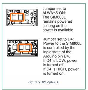
Power Enable Option: Jumper JP1
Jumper JP1 is used to select between having the
module always turned on as power is applied or have
the microcontroller control the regulator power and
hence power to the rest of the circuit. When the
microcontroller takes control (micro jumper is set at the
side labled“D4=1..”), it may turn off the output of the
regulator chip and hence no power is applied to the
SIM800L. This is done by applying a LOW on digital pin
- Power may turned back on by applying a HIGH on pin
- This scheme provides an actual hardware reset on
the SIM800L to occur and is useful in low power
applications or applications requiring reliability.
In contrast, when the micro jumper is set at the
ALWAYS ON side, the shield is always powered as long
as power is applied to the board.