

DESCRIPTION
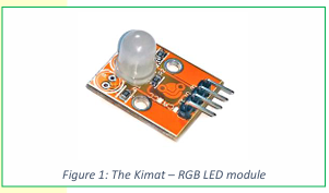
The RGB LED module is small compact module that
integrates an RGB LED with the necessary resistors and
breadboard/Arduino friendly pin headers. The diffused
RGB LED is able to display multiple colors using simple
digital output pins. PWM signals allow intensity control
of each color component and thereby producing even
more colors.
The RGB LED module is part of Layad Circuits’ Kimat
series of rapid prototyping products.

SCHEMATIC
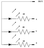

- FEATURES
- 8mm RGB LED with integrated resistors
- Compatible with 3.3V or 5V controllers
- Compact form factor, board dimensions:
- 20x23mm
- Standard 2.54mm pitch headers. Breadboard
- friendly.
- Comes in either Common Anode or Commode
- Anode variant.
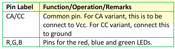
Usage of the module is straight forward. Connect each
color pin to a digital pin on the microcontroller. For a CA
board, connect the CA/CC pin to 5V. For CC variants,
connect this pin to GND. Turn each color on and off a
high or a low respectively. Generating PWM signals on
each color pin produces more colors.

Below is an example Arduino sketch demonstrating how the module may be used. This follows the connection as shown in figure 2. The sketch outputs 7 basic colors using simple low and high signals. The sketch is for the CA variant of the module. For CC variants, simply invert the LOWs with HIGHs and HIGHs with LOWs.
// sketch for CA variant
const byte PIN_R = 11;
const byte PIN_G = 10;
const byte PIN_B = 9;
void setup() {
pinMode(PIN_R,OUTPUT);
pinMode(PIN_G,OUTPUT);
pinMode(PIN_B,OUTPUT);
}
void loop() {
// RED
digitalWrite(PIN_R,LOW);
digitalWrite(PIN_G,HIGH);
digitalWrite(PIN_B,HIGH);
delay(1000);
// GREEN
digitalWrite(PIN_R,HIGH);
digitalWrite(PIN_G,LOW);
digitalWrite(PIN_B,HIGH);
delay(1000);
// BLUE
digitalWrite(PIN_R,HIGH);
digitalWrite(PIN_G,HIGH);
digitalWrite(PIN_B,LOW);
delay(1000);
// CYAN
digitalWrite(PIN_R,HIGH);
digitalWrite(PIN_G,LOW);
digitalWrite(PIN_B,LOW);
delay(1000);
// PURPLE
digitalWrite(PIN_R,LOW);
digitalWrite(PIN_G,HIGH);
digitalWrite(PIN_B,LOW);
delay(1000);
// YELLOW-GREEN
digitalWrite(PIN_R,LOW);
digitalWrite(PIN_G,LOW);
digitalWrite(PIN_B,HIGH);
delay(1000); 
// WHITE
digitalWrite(PIN_R,LOW);
digitalWrite(PIN_G,LOW);
digitalWrite(PIN_B,LOW);
delay(1000);
}
Generating PWM signals on the color pins produces
more colors. In case of the Saleng Uno/Arduino Uno,
pins 9~11 are capable of PWM signals using the
analogWrite() function. Of course, you can generate
PWM with some other method such as with timer
interrupts and still get the same results.
The following Arduino sketch demonstrates simple color
mixing using PWM signals.
// sketch for CA variant
const byte PIN_R = 11;
const byte PIN_G = 10;
const byte PIN_B = 9;
void rgb(byte r, byte g, byte b)
{
// use this for CA variant
analogWrite(PIN_R,255-r);
analogWrite(PIN_G,255-g);
analogWrite(PIN_B,255-b);
//for CC variant, use this instead:
//analogWrite(PIN_R,r);
//analogWrite(PIN_G,g);
//analogWrite(PIN_B,b);
}
void setup() {
pinMode(PIN_R,OUTPUT);
pinMode(PIN_G,OUTPUT);
pinMode(PIN_B,OUTPUT);
}
void loop() {
/*RED*/
rgb(255,0,0); delay(1000);
/*GREEN*/
/*BLUE*/
rgb(0,255,0); delay(1000);
rgb(0,0,255); delay(1000);
/*SKY BLUE*/  rgb(0,64,255); delay(1000);
/*PINK*/
rgb(255,0,64); delay(1000);
/*CYAN*/
/*YELLOW*/
/*PURPLE*/
/*ORANGE*/
/*WHITE*/
/*VIOLET*/
rgb(0,128,255); delay(1000);
rgb(128,96,0); delay(1000);
rgb(255,0,255); delay(1000);
rgb(255,32,0); delay(1000);
rgb(255,255,255); delay(1000);
rgb(48,32,160); delay(1000);
/*BLUE-GREEN*/rgb(0,255,64); delay(1000);
/*OFF*/
rgb(255,128,32);
}