

OVERVIEW
LC-084 Power Supply Kit
User Guide
The LC-084 Power Supply Kit is designed to provide a stable direct current power to supply electric loads of up to 1A. The output voltage of the
circuit shall depend on the regulator IC selected from the options available. The kit is a collection of electronic components, connectors and a PCB
board meant to be assembled by hand. As such, soldering is required. This document provides a brief description of the circuit, its schematic
diagram and a guide on the assembly and testing. While this is designed primarily as a learning kit, the final assembled product may be used as a
actual power source.
WARNING!
The use of a soldering and sharp tools is required to assemble this kit.
Risk of fire and injury may result from improper usage of this kit.
Proper safety precautions must be exercised at all times.
Before you continue, do note that this kit may involve high voltages that may
Impose risk of electrocution. Do not assemble, test or use this kit if you
do not have sufficient electrical safety background or do not have assistance
from a professional.
KIT CONTENTS
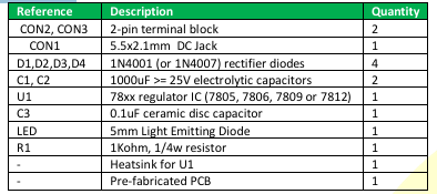
The components in the kit are tabulated below:
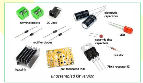
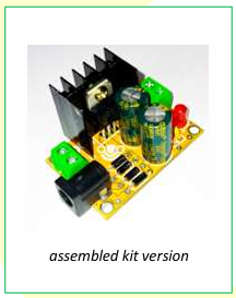
The kit may be available in 2 versions, an unassembled and assembled version. Contact us for availability.

OUTPUT
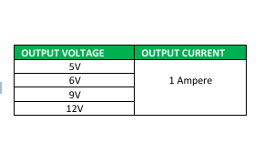
The user may select from available fixed voltage outputs listed below. Check with us for
availability of other output voltages. The circuit is designed for up to a maximum of 1A
output current. Note that this is a maximum surge current rating. The circuit is not meant to
be operated at this maximum current continuously. Refer to the individual datasheet of the
specific 78xx IC of your kit for the other electrical parameters. The load is attached into the
output screw terminal block labeled CON2 on the PCB.
INPUT
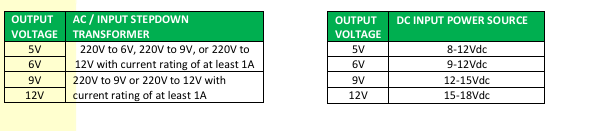
The kit requires an external source of power of either AC or DC supply. A step down transformer with a ratio of 220:6 up to 220:12 with current
rating of at least 1A may be used. DC power sources such as that from an AC/DC adapter may also be used. See the following table for the
recommended power sources. The input voltage of the circuit must be at least be 2-3.2V higher than the selected output due to the dropout
voltage required by the regulator and rectifiers. The input power source may be applied to either the input screw terminal block CON1 or the
5.5×2.1mm DC jack CON3
CIRCUIT
The schematic diagram below shows the circuit implemented in the kit. This is a basic, fixed output, linear voltage regulated circuit where the input
voltage is applied into D1-D4 configured as a full bridge rectifier. An AC sinewave input is transformed into a pulsating DC at the output of the
rectifier which is then smoothed out by the filter C1. A DC input shall remain DC after the rectifier circuit but less around 1.2V dropped by the
rectifier diodes. The voltage is then regulated by the 78xx IC to maintain the desired output voltage. The output capacitors C2 and C3 ensures
stability, additional filtering and decoupling. The LED with the series resistor R1 indicates when power is present at the output and also ensures
that the circuit meets the minimum load current, typically 5mA, as required by the regulator IC. The heatsink allows the 78xx IC to safely dissipate
the heat. Depending on your target application, active cooling may be additionally implemented with a DC fan.


ORIENTATION GUIDE
Refer to the orientation of the components below. R1 and C3 may be installed in any orientation.

ASSEMBLY SUGGESTIONS
For the unassembled version, the following suggestion may help the user in the assembly of the board.
Install D1-D4 and R1 into the board. Beware of the diode polarity.
o Bend both pins to 90 degrees, with both pins facing one direction
o Insert the components into the top side/component side of the PCB. Hold down using adhesive tape.
o Maintain a space of around 1mm between the PCB and the body of the component
o Solder one pin and check if the installation is okay. Adjust if necessary.
o Solder the other pin to finalize the installation
o Cut the extra length of the pins using a side cutter-
Install C3 and the LED. Follow the orientation of the LED.
o Solder one pin and check if the installation is okay. Adjust if necessary.
o Solder the other pin to finalize the installation
o Cut the extra length of the pins using a side cutter
Install the terminal blocks and the DC Jack
o Check that the wire slots of the terminal blocks are facing outward.
o Solder one pin and check if the installation is okay. Adjust if necessary.
o Solder the other pin(s) to finalize the installation
o Cut the extra length of the pins using a side cutter
LC-084 Power Supply Kit
User Guide
Install two electrolytic capacitors. Beware of the capacitor polarity. \
o The negative side has “-“markings on the body while the positive side is the longer pin.
o Solder one pin and check if the installation is okay. Adjust if necessary.
o Solder the other pin to finalize the installation
o Cut the extra length of the pins using a side cutter
Install the tab of the 78xx regulator chip into the heatsink via the slot provided using a 3mm screw
o Install the regulator with the heatsink into the PCB and hold down with adhesive tape
o Solder one of the heatsink stand and check if the components are aligned
o Solder the other heatsink stand
o Solder the 3 terminals of the regulator
o Cut the extra length of the regualtor pins using a side cutter
ASSEMBLED PRODUCT- The following shows pictures of the assembled product

