OVERVIEW
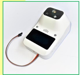
The LC-081 or Layad Circuits’ Serial Temperature Scanner
is a UART (“Serial”) interfaceable non-contact thermal
reader. The device is designed to be used with a larger
system with a any UART/Serial-capable host
microcontroller such as Arduino or Raspberry Pi. It comes
with all the necessary electronics to perform
temperature scanning of people or objects and output
the reading into its seven segment display and UART port
via the attached female pinheader-terminated wires. The
LC-081 comes in 3 distinct Modes and can use either
Fahrenheit and Celsius as its unit of measurement.
FEATURES
- Ready interface port for microcontrollers via UART
serial interface.
o 9600 baud rate, 8 data bits, no parity,
and 1 stop bit
o Simple serial text protocol
o TX only at 3.3V logic - Modes
o Body Mode
o Surface Mode
o Counting Mode - 2 Units of measurement
o Celsius
o Fahrenheit - Automatic Alarm for “high” readings
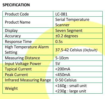
- Accuracy : ±0.2 degrees
- Measurement Distance: ~5-10 cm
- Input power: 5V
- Typical Power Consumption: <200mA
- Peak Power Consumption: <450mA
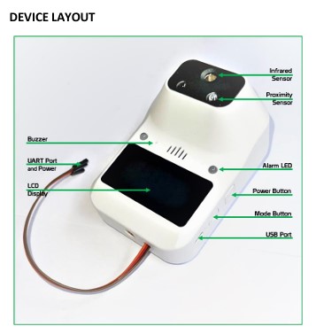
- Integrated casing, LCD readout and buttons
- Works with both 5V and 3.3V logic
- Response Time: ~0.5sec
- Arduino, Raspberry Pi, ESP8266, ESP32 compatible
PIN FUNCTIONS
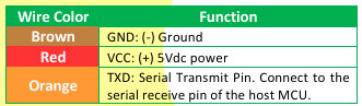
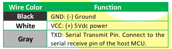
There are two sets of color codes for the wired header
port of the device. Your unit should come in either one
of them. Refer to the tables below.
Code 1: Brown-Red-Orange
Code 2: Black-White-Gray
The device aims to replace sensor-module solutions
(e.g. MLX90614) by improving upon the issues
accompanying such sensor-only implementation
including the need for a separate proximity sensor,
display, power regulator, level shifter, buzzer,
enclosure, warning LEDs, and audio notification. It also
simplifies use for human body temperature
measurements as the device is pre-calibrated for such
Finally, the difficulties associated with I2C
implementation such as bus sharing issues or the need
to for an external library are eliminated.
NOTE: This device is meant for educational purposes
only (e.g. product prototypes) and does not replace
medical or industrial grade thermometers.


UART/ SERIAL PORT
The Device has no RXD terminal as it only outputs data
on its TXD terminal/pin. Although the power required is
5V, the TXD signal is at 3.3V logic, therefore, it may be
used directly with 5V logic host controller (e.g. Arduino
Uno, Mega, Nano) or with a 3.3V host such as Raspberry
Pi, ESP8266 or ESP32 without the need for a level shifter
circuit. The baud rate is 9600 at the standard
configuration of 8 data bits, no parity and 1 stop bit.
While the casing has a battery slot, it has no use. The
device is designed to be powered at the wired terminals.
Any battery implementation should consider powering
the whole system, including the host microcontroller.
SIZE VARIANTS
The device comes in 2 sizes, the “large” and the “small”
variant. Please contact Layad Circuits for additional
information.
USER BUTTONS AND POWER SWITCH
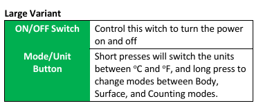
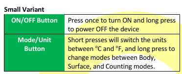
The user buttons and their functions are described in the
table below.
POWER REQUIREMENTS
The unit should be powered from a regulated 5V power
source that can reliably deliver current of up to 450mA.
Powering at the Wired Terminal
The LC-081 maybe powered from the 5V pin of most
Arduino board as these are typically rated at 1A.
However, care should be exercised when there are other
electrical loads being supplied by the Arduino regulator
or if the device is to be used in the long term. We
recommend using a separate 5V regulator circuit that can
supply ≥ 500mA such as an LM7805 with heatsink or a
buck converter module such as LM2596. Refer to the
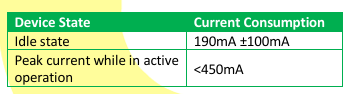
current consumption table below:
MODES
The LC-081 has 3 Modes that serves different purposes
as described below:
- Body (B) Mode
This mode is designed for scanning human body
temperature. It is the primary purpose of this device
and has a range of 32-42 oC or 89.6-107.6 oF. It has an
alarm function where readings that reach 37.5-42 oC or
99.5- 107.6 oF (default setting) will generate an alarm by
flashing the front red lights continuously for 5 seconds.
Powering at the USB port
A microUSB port is also available as power source. Please
check that your microUSB power supply has a 5V output.
Some smart power supplies may output more than 5V
and should therefore not be used with this device.
Warning: When the microUSB port is powered, do not
connect the VCC wire to another 5V power source. Only
the TXD and GND should be connected to the host
microcontroller in this case.


The scanner will be disabled within that 5 second. A
voice alarm is also generated.

- CR – carriage return character (0x0D)
- LF – line feed / new line character (0x0A)
Examples:
@,025.4,C,B,#
@,077.7,F,B,#
- Counting (C) Mode
In this mode, the Serial Temperature Scanner act as a
person/object counter. It will count and beep each time
someone or something was detected within its
proximity. Be noted that changing the mode or power
cycling will reset the counter.
When Body mode is set, the format of the output serial
data is as follows:

@,,,,# Where: • Temperature – the temperature reading in 3 whole digits and 1 decimal digit • Unit – either ‘C’ (0x43) for Celsius or ‘F’ (0x46)for Fahrenheit • Mode – ‘B’ (0x42) for body mode • CR – carriage return character (0x0D) • LF – line feed / new line character (0x0A) Examples: @,036.5,C,B,# @,097.7,F,B,# 2. Surface (S) Mode This mode is designed to measure temperature of objects thus having a much wider range. It has a tested coverage of 0.3- 99.8 oC or 32.5-212.4 oF.

When Counting mode is set, the format of the output serial data is as follows: @,,,,# Where: • Count – 5 digit count • Unit – ‘N’ (0x4E) for no unit • Mode – ‘C’ (0x43) for counting mode • CR – carriage return character (0x0D) • LF – line feed / new line character (0x0A) Example: ALARMS @,00001,N,C,# When HI or Lo is displayed in the front panel accompanied by a flash of red lights, this indicates that the measurement is out of range.

@,,,,# Where: • Temperature – the temperature reading in 3 whole digits and 1 decimal digit • Unit – either ‘C’ (0x43) for Celsius or ‘F’ (0x46)for Fahrenheit • Mode – any of the following: ‘S’ (0x53) for surface mode
The measured temperature is higher than the specified
range of 42 oC/107.6 oF for Body and 99.8 oC /212.4 oF
for Surface.



- Turn on the power while the button is still
pressed - The firmware version momentarily displays on
the front panel. At this point release the button - The display will then show the dots lighting up
in sequence. At this point press and hold the
button again to enter the menu
Small Variant: - Press and hold both power button and mode
button to enter the settings menu.
A sequence of settings will be presented to the user
after entering the menu. - To change value/setting of each menu – short
press the buttons - To save the current selected value/setting –
press and hold both buttons for small variant or
the mode button for large variant. The next
setting is automatically presented.
The measured temperature falls below the specified
range of 32 oC/89.6 oF for Body and 0.3 oC/32.5 oF for
Surface.
The settings are as follows. Not all settings may appear
on a particular variant.
- High Temperature Alarm Setting
This sets the temperature at which the High
Temperature Alarm, e.g. temperature considered as
fever. The default is 37.5 Celsius. - Low temperature Setting
This setting has 2 options, Lo/nor and 32.0. It is
recommended to keep this setting in the Lo/nor option.
- LO or nor – when temperature measured is 32.0
°C or lower, an alarm is generated and the “Lo”
is displayed on the front panel. This indicates
that the measurement is out of range and
should be repeated. The serial data shall send
out the error code (refer to MODES section).
This is the default setting. “LO” and “nor” are
the same. - 32.0 – In this option, the device will attempt to
output whatever is measured out into the serial
The serial output date will show an Error code shown below: @,00000,0,0,# Where: • @,00000,0,0,# – this is the error code • CR – carriage return character (0x0D) • LF – line feed / new line character (0x0A) Example: FACTORY RESET @,00000,0,0,# Press and hold the power button for 6 secs until rST is displayed. It will reset the High Temperature Setting and Low temperature Setting to the default settings. SETTINGS MENU A series of settings may be adjusted by accessing the settings menu. We do not recommend changing any of these. However, we are enumerating them in this section for reference. Note that specific variants may omit certain settings. To access the menu, follow the procedure below: Large Variant: • Turn the power off • Press and hold the mode button
- Language setting – Selects between Chinese (CH),
English (EN), Italian (IT), Korean (HR), Spanish (SP) and
other languages. The default is English (EN). - Volume setting:
Select Vo0 to Vo5 volume level. Vo5 is the highest and
Vo0 is silent. The default is Vo2 - Buzzer Setting
Choose between a short beep (d1) and a doorbell tone
(d0) on every detected proximity. The default is d1 - S-setting
Do not change this parameter. This is a reserved setting. - Automatic Shutdown
In A1 option, the device will automatically shutdown if
no operation is performed in 12 hours. Power cycle or
long press the power button to wake the device up. A0
option disables this feature and keeps the device awake
indefinitely. - Firmware
Display the firmware version number - Menu Exit
After switching to the version number, long press the
two buttons for the small variant, or the mode button
for the large variant, to exit the settings menu. The
device will automatically exit if no operation is detected
within 10 seconds.
APPLICATION NOTES
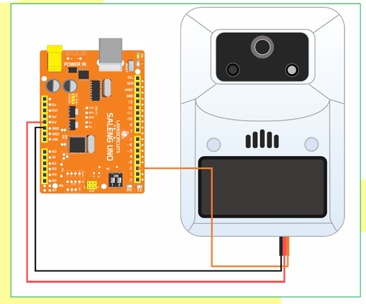
EXAMPLE WIRING: LC-081 TO ARDUINO UNO
LC-081 SERIAL TEMPERATURE SCANNER
User Guide
APPLICATION NOTES
In this diagram, the LC-081 is connected to an Arduino UNO using SoftwareSerial with RXD define at pin 2 and TXD
defined at pin 3. Although we are declaring pin 3 as the TXD of the Arduino, we do not need it for the LC-081.
EXAMPLE CODE #1
This is a simple code used to print the raw data received from the LC-081 into the Arduino Uno’s hardware serial port
and viewed from the Serial Monitor set to 9600 baud rate. Wiring follows the previous diagram.
#include <SoftwareSerial.h>
SoftwareSerial IRscanner(2,3);//RX,TX
void setup()
{
Serial.begin(9600); // serial monitor port
IRscanner.begin(9600); //LC-081 serial port
}
void loop()
{
while (IRscanner.available()>0)
{
Serial.write(IRscanner.read());
}
}
This code stores the data received from the thermal scanner and converts it into a float variable. Wiring follows the
previous diagram.
#include <SoftwareSerial.h>
SoftwareSerial IRscanner(2, 3);  // RX, TX
float temperature;
void setup()
{
Serial.begin(9600);
IRscanner.begin(9600);
}
//arduino serial port
//IR scanner serial port
void loop()
{
while (IRscanner.available()>0)
{
static char IRreading[14];
static unsigned int reading_position=0;
char store=IRscanner.read();
if( store!='\n' && reading_position<13 )
{
IRreading[reading_position]=store;
reading_position++;
//store data received as a whole
//store the whole data as an array
}
else
{
//print temperature
static char store_number[6]="";
memcpy(store_number,&IRreading[2],5);  //store only the numbers into an array
temperature = atof(store_number);
//convert the numbers received as float
Serial.print(temperature,1);
//print with 1 decimal digit
//print unit
if(IRreading[8]=='C'){ Serial.print(" Celsius, "); }
else if(IRreading[8]=='F'){ Serial.print(" Fahrenhiet, "); }
else{Serial.print(" no unit, ");}
//print mode
if(IRreading[10]=='B'){ Serial.println("BODY"); }
else if(IRreading[10]=='S'){ Serial.println("SURFACE"); }
else if(IRreading[10]=='C'){ Serial.println("COUNTING"); }
else{Serial.println("ERROR");}
reading_position=0;
//reset for next message
while (IRscanner.available()) { IRscanner.read(); }//clear serial buffer
}
DIRECT TO COMPUTER / RASPBERRY PI
LC-081 SERIAL TEMPERATURE SCANNER
User Guide
If the device is to be used with a computer as its controller, then a simple UART-to-USB converter module or dongle may
be used. Below is an example using the Kimat USB-TTL converter dongle. Other dongles may be used such as those
based around FTDI, Prolific or CH340x chips.
Although a Raspberry Pi board has raw UART pins at its GPIO headers where we can interface the LC-081 directly, there
may be use cases where a USB connection is necessary or desirable. In such case, the same UART-to-USB converter
circuit is required.
In both cases above, the driver software of the converter chip drivers must be installed into the host
computer/Raspberry Pi.
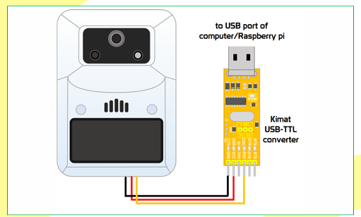
Once connected the data can be read out of the serial port (COMx in Windows) set at a baud rate of 9600, 8 databits, No
parity and 1 stop bit. Program the application software to receive this data and process or present it accordingly. This
computer/Raspberry Pi application is beyond the scope of this document.