
OVERVIEW
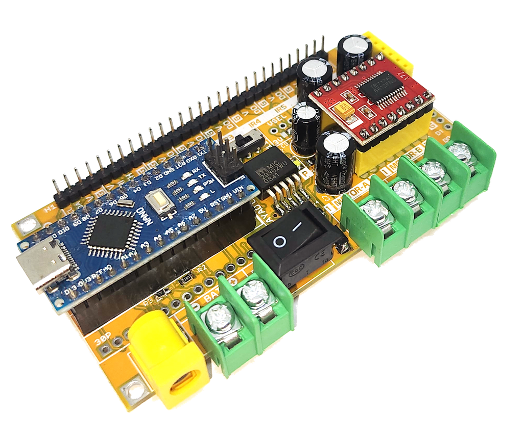
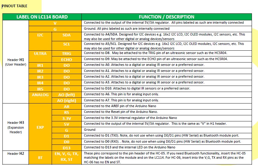
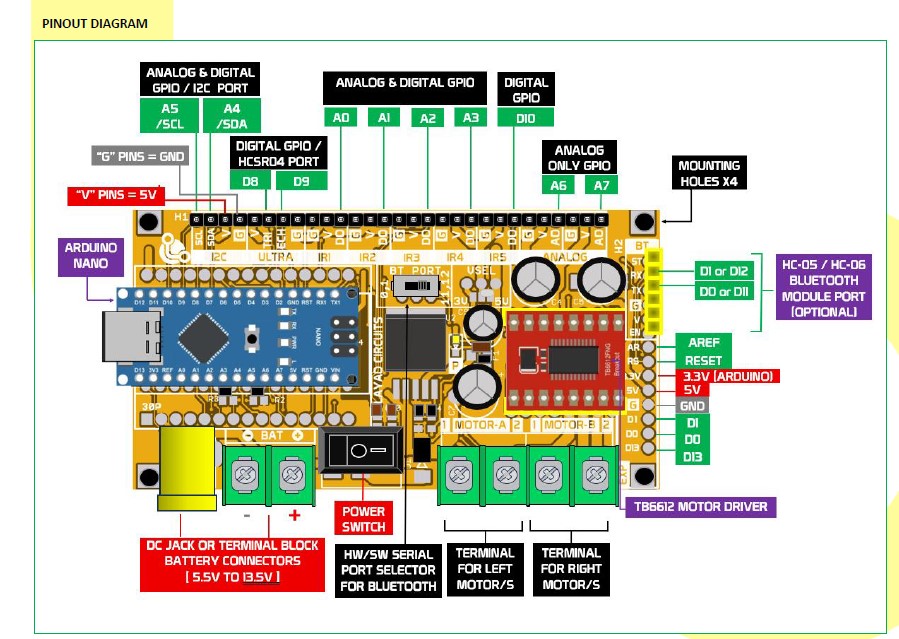
The LC114 Mini Robot Controller (“MiniCon”) is a fully integrated board for mobile robot builds. The board has a slot for an Arduino Nano as microcontroller and TB6612FNG module as motor driver. An internal 5V regulator with 3A maximum current is embedded allowing more sensors and devices. While the board is designed for two 3.7V Lithium batteries in series for a nominal series voltage of 7.4V, the LC114 may accept a wide input voltage from 5.5V up to 13.5V. This makes 2 or 3 Li Ion or Li Po batteries in series compatible with the board. A slot for either the HC-05 or HC-06 Bluetooth module is available on board and may be routed to the Arduino Nano’s hardware serial (UART) or software serial.
Overall, the LC114 simplifies mobile robot wiring: users only need to connect the battery, motors and sensors using the ready made connectors on board. All others are wired internally for a clean implementation.
FEATURES
•
All-in-One Integration: all essential circuits in one board
•
Wide Input Power: 5.5V to 13.5V
•
MCU slot: Arduino Nano
•
Motor Driver Slot: TB6612FNG module
•
Bluetooth Module: HC-05 or HC-06
•
Embedded 3A, 5V regulator
•
Overcurrent, Reverse Polarity protection
•
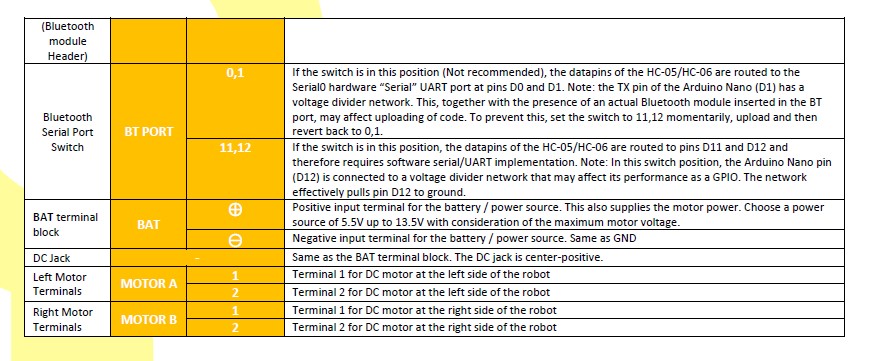
Switchable Bluetooth module port
•
Integrated power switch, DC Jack, terminal blocks and pin headers
•
User headers: I2C port, Ultrasonic sensors, 5x IR sensors, 2x analog sensors
•
From STEM/Engineering Classroom to Competition Level
MOTOR DRIVER
If you are replacing or proving your own TB6612FNG, please limit your motor voltage (and battery) to 9V. If this was bought with the motor driver board included, the motor voltage may reach a maximum of 13.5V.
APPLICATION NOTES
Line Follower / Line Tracing Robot
•
Sensor Selection Guide
o
Minimum of 2 IR sensors are needed for basic line tracer robot.
o
IR1, IR2, IR3 and IR4 are all capable of both analog (ADC) inputs, digital inputs/outputs.
o
IR5 is digital only I/O.
o
The ANALOG pins (A6 and A7) are analog input only.
o
For PID with 5-Channel digital IR sensor, simply use IR1 to IR5
o
Incase all 8 analog pins are needed (e.g. 8-channel analog sensor with PID), then use A4 (SDA), A5(SCL), left analog channel (A6) and right analog channel (A7) together with A0-A3 at IR1-IR4.
o
For 8 to 16-channel sensors with 5 control lines, you may use the DO pins of IR1 to IR5
o
The”Ultra” header may be used with an HCSR04 if an ultrasonic sensor is needed.
•
Select high speed motors. The LC114 is also compatible with N20 motors (6V/12V) paired with 2S batteries. See example in the coming sections.
Sumobot
•
Select high torque motors. The TB6612FNG can handle up to 1.2A continuous current and 3.2A peak surge current.
•
For opponent tracking, use either the ULTRA when using an ultrasonic sensor or any of the analog pins for IR Analog Distance sensors such as the GP2Y0A21YK0F(IR1-IR4 or SDA and SCL)
•
For border line tracking with a digital output IR sensor, use Any of the free pins (IR1 – IR5 etc.)
•
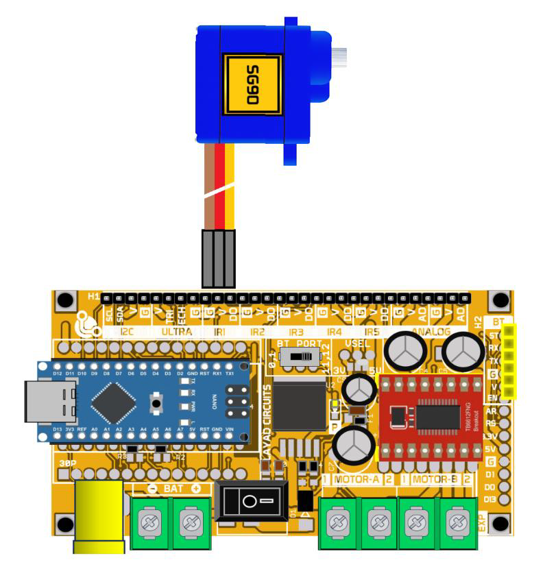
If servo motors are needed, the IR1-IR5 pins in the H1 header are sorted according to the pin out of standard servo motors. E.g. when using IR4 for a servo motor, use the following connections G=Brown Wire, V=Red Wire, DO=Yellow/Orange wire. See the Servo Motor Usage section for details.
Maze Solver / Obstacle Avoidance Robot
•
Track obstacles using either the ULTRA port with an ultrasonic sensor or any of the analog pins for IR Analog Distance sensors such as the GP2Y0A21YK0F (IR1-IR4 or SDA and SCL)
•
For a 3-ultrasonic sensor setup (left, center, right), use the ULTRA port for the center sensors, the I2C (TRIG=A5 and ECHO=A4) for the left sensor. For the right, use the DO of IR1 as TRIG and DO of IR2 as ECHO of the right sensor
Remote Controlled / Soccer Robot
•
Insert an HC-05 or HC-06 into the BT header
•
If servos are needed (e.g. for ball manipulation), see the servo usage section below
Camera Equipped Robot
•
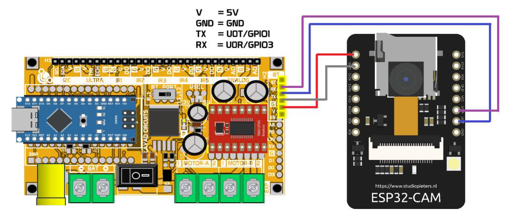
In place of the HC-05, the user may install a Serial-interfaced Camera such as the ESP32-Cam or even the ESP32-S3 Cam. Since the BT port has 3.3V level shifter, directly into the BT port as shown:
USING SERVO MOTORS
To use servo motors such as SG90, MG90 or MG996R with the LC114 board, use the 5V pin available on the “V” pins as power source for the servos and the “DO” pins as servo signal pins. See the example diagram below
Notes on using servo motors:
•
the 5V pin can supply a maximum of 3A and subject to power source/battery discharge capabilities.
•
In general, two SG90s or MG90s could be handled simultaneously (depending on mechanical load and battery ).
•
Limiting the number of servos moving at the same time may also help reduce current requirements.
•
If you are using software serial with servo applications, check for possible library conflicts
EXAMPLE APPLICATIONS
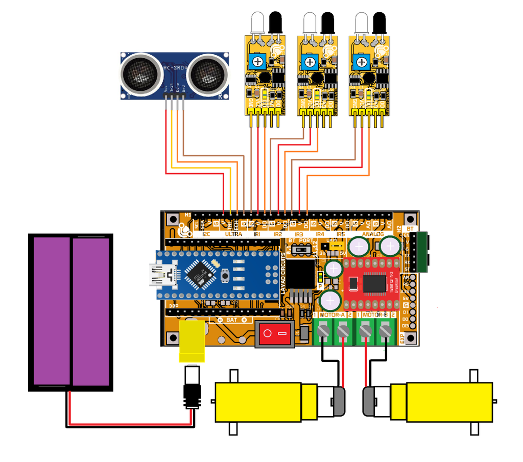
This section discusses 3 possible applications for the LC114 : (1) Line Tracing / Follower Robot , (2) RC Robot and (3) Obstacle Avoiding / Maze Solver Robot. Follow the suggested wiring diagram shown below for the examples provided in this document. Note the following considerations:
•
Sensor not required by the application/configuration need not be wired. They are shown below to demonstrate how each sensor may be connected
•
Line tracing robots do not need the ultrasonic sensor for this particular example
•
The table below defines the connections needed for each robot configuration based on the example programs provided. The user may change connections according to their specific needs.
•
Connections for the motors and battery remain the same for all robot configurations


•
IR sensors need re-calibration within the area of application. Avoid high infrared sources such as direct ambient sunlight as these may drastically affect sensor readings. To calibrate the LC IR prox sensors or the Saleng Tracker modules:
o
Connect V and G to the IR sensor to power the module.
o
Keep the field of view of the sensors cleared of reflective surfaces including your fingers
o
Slowly rotate the blue-white potentiometer on the sensor using a screw driver.
o
Find the direction where the onboard LED turns off and stop.
o
Rotate the potentiometer in the opposite direction until the LED turns on
o
Rotate the potentiometer back to the other direction and stop just as the LED turns off. This spot is what you want. Test by waving your hand Infront of the sensor field of view and see if the onboard LED reacts correctly
SOFTWARE EXAMPLES
The following examples demonstrate how this kit may be used in different configurations. These however, do not limit the application of the robot kit.
Remote Control Robot– this robot uses the HC05/HC06 Bluetooth module to communicate with a smart phone where the remote control user interface app runs. This example uses the app named BT Car Controller-Arduino/ESP developed by Giristudio and downloadable from Google Play Store. Similar free applications are available online and may require editing of the character commands in the code when used with this example.
#include <SoftwareSerial.h>
SoftwareSerial bluetooth(12, 11); // RX, TX
byte PIN_IN1 = 2;
byte PIN_IN3 = 7;
byte PIN_IN2 = 4;
byte PIN_IN4 = 5;
byte PIN_ENA = 3;
byte PIN_ENB = 6;
const byte speedval=255; // edit as needed. 255=full speed.
void speedSetting(byte val)
{
analogWrite(PIN_ENA, val);
analogWrite(PIN_ENB, val);
Serial.print("Speed: ");
Serial.println(val);
}
void forward()
{
Serial.println(F("ACTION: FORWARD"));
speedSetting(speedval);
digitalWrite(PIN_IN1, LOW);
digitalWrite(PIN_IN2, HIGH);
digitalWrite(PIN_IN3, LOW);
digitalWrite(PIN_IN4, HIGH);
}
void backward()
{
Serial.println(F("ACTION: BACKWARD"));
speedSetting(speedval);

digitalWrite(PIN_IN1, HIGH);
digitalWrite(PIN_IN2, LOW);
digitalWrite(PIN_IN3, HIGH);
digitalWrite(PIN_IN4, LOW);
}
void turnright()
{
Serial.println(F("ACTION: TURN RIGHT"));
speedSetting(speedval);
digitalWrite(PIN_IN1, LOW);
digitalWrite(PIN_IN2, HIGH);
digitalWrite(PIN_IN3, HIGH);
digitalWrite(PIN_IN4, LOW);
}
void turnleft()
{
Serial.println(F("ACTION: TURN LEFT"));
speedSetting(speedval);
digitalWrite(PIN_IN1, HIGH);
digitalWrite(PIN_IN2, LOW);
digitalWrite(PIN_IN3, LOW);
digitalWrite(PIN_IN4, HIGH);
}
void motorstop()
{
Serial.println(F("ACTION: STOP"));
digitalWrite(PIN_IN1, LOW);
digitalWrite(PIN_IN2, LOW);
digitalWrite(PIN_IN3, LOW);
digitalWrite(PIN_IN4, LOW);
}
void setup()
{
Serial.begin(9600);
bluetooth.begin(9600);

PIN_IN1, OUTPUT);
pinMode(PIN_IN2, OUTPUT);
pinMode(PIN_IN3, OUTPUT);
pinMode(PIN_IN4, OUTPUT);
pinMode(PIN_ENA, OUTPUT);
pinMode(PIN_ENB, OUTPUT);
motorstop();
Serial.println(F("================"));
Serial.println(F(" MINICON Ready "));
Serial.println(F("================"));
}
void loop()
{
if (bluetooth.available() > 0)
{
char c = bluetooth.read();
Serial.print(F("received: "));
Serial.prinln(c);
if (c == 'F')
{
forward();
}
else if (c == 'S')
{
motorstop();
}
else if (c == 'R')
{
turnright();
}
else if (c == 'r')
{
motorstop();
}
else if (c == 'L')
{

}
else if (c == 'B')
{
backward();
}
else
{
Serial.println(F("UNKNOWN COMMAND"));
}
Serial.println(F("----------------------"));
}
}
Line Tracing Robot with 2 IR Sensors – this robot uses 2 IR sensors installed at the left side and right side. When the dark line is detected by the left sensor, the robot steers left and when the sensor at the right detects the line, the robot steers right. When the line is not detected by the senors, it is assumed that the robot is centered on the line and therefore it moves forward. This 2-sensor line tracer is simpler than the 3-sensor line tracer.
byte PIN_IN1 = 2;
byte PIN_IN3 = 7;
byte PIN_IN2 = 4;
byte PIN_IN4 = 5;
byte PIN_ENA = 3;
byte PIN_ENB = 6;
byte PIN_SENSOR_L = A0;
byte PIN_SENSOR_R = A1;
byte BLK = LOW;
byte WHT = HIGH;
byte sensorL, sensorR;
void speedSetting(byte val)
{
analogWrite(PIN_ENA, val);
analogWrite(PIN_ENB, val);
Serial.print("Speed: ");
Serial.println(val);
}
void forward()
{
speedSetting(75); //tune
digitalWrite(PIN_IN1, LOW);
digitalWrite(PIN_IN2, HIGH);
digitalWrite(PIN_IN3, LOW);
digitalWrite(PIN_IN4, HIGH);
}
void backward()
{
speedSetting(70); //tune
digitalWrite(PIN_IN1, HIGH);
digitalWrite(PIN_IN2, LOW);
digitalWrite(PIN_IN3, HIGH);
digitalWrite(PIN_IN4, LOW);
}
void turnleft()
{
speedSetting(70); //tune
digitalWrite(PIN_IN1, LOW);
digitalWrite(PIN_IN2, HIGH);
digitalWrite(PIN_IN3, HIGH);
digitalWrite(PIN_IN4, LOW);
}
void turnright()
{
speedSetting(70);
digitalWrite(PIN_IN1, HIGH);
digitalWrite(PIN_IN2, LOW);
digitalWrite(PIN_IN3, LOW);
digitalWrite(PIN_IN4, HIGH);
}

void motorstop()
{
digitalWrite(PIN_IN1, LOW);
digitalWrite(PIN_IN2, LOW);
digitalWrite(PIN_IN3, LOW);
digitalWrite(PIN_IN4, LOW);
}
void setup() {
Serial.begin(9600);
pinMode(PIN_IN1, OUTPUT);
pinMode(PIN_IN2, OUTPUT);
pinMode(PIN_IN3, OUTPUT);
pinMode(PIN_IN4, OUTPUT);
pinMode(PIN_SENSOR_L,INPUT);
pinMode(PIN_SENSOR_R,INPUT);
delay(1000);
Serial.println(">");
}

void loop()
{
// read the sensors
sensorL = digitalRead(PIN_SENSOR_L);
sensorR = digitalRead(PIN_SENSOR_R);
//decide what action to take base on
//what we read from the sensor
if((sensorL == BLK) && (sensorR == WHT))

{
turnleft();
}
else if((sensorL == WHT) && (sensorR == BLK))
{
turnright();
}
else if((sensorL == WHT) && (sensorR == WHT))
{
forward();
}
else if((sensorL == BLK) && (sensorR == BLK))
{
motorstop();
}
}
Line Tracing Robot with 3 IR Sensors – this robot uses 3 IR sensors installed at the left side, center and right side. When the dark line is sensed by the center sensor, the robot move forward. When the dark line is detected by the left sensor, the robot steers left and when the sensor at the right detects the line, the robot steers right. This line tracer has smoother movement compared to a 2-sensor line tracer.
byte PIN_IN1 = 2;
byte PIN_IN3 = 7;
byte PIN_IN2 = 4;
byte PIN_IN4 = 5;
byte PIN_ENA = 3;
byte PIN_ENB = 6;
#define SENSOR_L A0
#define SENSOR_R A1
#define SENSOR_C A2
#define BLK LOW // line
#define WHT HIGH // background
byte sensorL, sensorC, sensorR;
void speedSetting(byte val)
{
analogWrite(PIN_ENA, val);
analogWrite(PIN_ENB, val);
Serial.print(F("Speed: "));
Serial.println(val);
}
void forward()
{
speedSetting(80); // tune.this value
digitalWrite(PIN_IN1, LOW);
digitalWrite(PIN_IN2, HIGH);
digitalWrite(PIN_IN3, LOW);
digitalWrite(PIN_IN4, HIGH);
}
void backward()
{speedSetting(70); // tune.this value
digitalWrite(PIN_IN1, HIGH);
digitalWrite(PIN_IN2, LOW);
digitalWrite(PIN_IN3, HIGH);
digitalWrite(PIN_IN4, LOW);
}
void turnleft()
{
speedSetting(70); // tune.this value
digitalWrite(PIN_IN1, LOW);
digitalWrite(PIN_IN2, HIGH);
digitalWrite(PIN_IN3, HIGH);
digitalWrite(PIN_IN4, LOW);
}
void turnright()
{
speedSetting(70); // tune.this value
digitalWrite(PIN_IN1, HIGH);
digitalWrite(PIN_IN2, LOW);
digitalWrite(PIN_IN3, LOW);
digitalWrite(PIN_IN4, HIGH);
}
void motorstop()
{
digitalWrite(PIN_IN1, LOW);
digitalWrite(PIN_IN2, LOW);
digitalWrite(PIN_IN3, LOW);
digitalWrite(PIN_IN4, LOW);
}
void setup() {
Serial.begin(9600);
pinMode(PIN_IN1,OUTPUT);
pinMode(PIN_IN2,OUTPUT);
pinMode(PIN_IN3,OUTPUT);
pinMode(PIN_IN4,OUTPUT);
pinMode(SENSOR_L, INPUT);
pinMode(SENSOR_C, INPUT);
pinMode(SENSOR_R, INPUT);
motorstop();
delay(3000); // add 3s delay
Serial.println(F(">"));
}
void loop()
{
// read and store all sensors
sensorL = digitalRead(SENSOR_L);
sensorC = digitalRead(SENSOR_C);
sensorR = digitalRead(SENSOR_R);
if(sensorL == BLK && sensorC == BLK && sensorR == BLK)
{
backward(); // assume we overshot line
}
else if(sensorL == WHT && sensorC == BLK && sensorR == BLK)
{
turnleft();
}
else if(sensorL == WHT && sensorC == BLK && sensorR == WHT)
{
// all white, move forward (depends)
forward();
}
else if(sensorL == BLK && sensorC == BLK && sensorR == WHT)
{
turnright();
}
else if(sensorL == BLK && sensorC == WHT && sensorR == BLK)
{
forward();
}
else if(sensorL == WHT && sensorC == WHT && sensorR == BLK)
{
turnleft();
}
else if(sensorL == WHT && sensorC == WHT && sensorR == WHT)
{
forward();
}
else if(sensorL == BLK && sensorC == WHT && sensorR == WHT)
{
turnleft ();
}
}
CIRCUIT USAGE AND SAFETY GUIDELINES
1.
All “G” pins connect to the same ground and “V” pins connect to 5V / 3A regulator
2.
The BT PORT switch defines which serial port shall be used by the Bluetooth module HC05 connected at the BT header. Unless the user is aware of its implications, do not change the default setting set to “11,12” side.
3.
The BT header hosts the HC-05. In case of replacement, ensure correct orientation of the module with respect to the BT header.
4.
The DC jack is designed for connection to the battery pack. The connector is center-positive and is in parallel with the BAT terminal block.