


DESCRIPTION
APPLICATIONS NOTES
The 3 LED module is small compact module that
integrates 3 LED’s with the necessary resistors and
breadboard/Arduino friendly pin headers.
The 3 LED module is part of Layad Circuits’ Kimat series
of rapid prototyping products.
This module contains a very simple circuit – 3 standard
5mm LED’s with current limiting resistors. Simple things
may prove troublesome to build though when you have
to do it often or when your project is time critical. This
is especially true for something very useful as LED’s.
This is why we have this module. This has been used
extensively as an indicator from simple 3 channel digital
state tester to power indicators.

- FEATURES
- 3x 5mm LED’s with integrated resistors
- Compatible with 3.3V or 5V controllers
- Compact form factor, board dimensions:
- 20x23mm
- Standard 2.54mm pitch headers. Breadboard
- friendly.
Wiring and Testing
You may always use connectors (or breadboard) for the
pins and connect them individually to whichever GPIO
or voltage source you want to use. For Arduino users, a
trick for avoiding the use of wires is to employ 1 digital
pin as a ground pin by setting it as an output and
initializing it to the low state. This will allow you to
insert the module into any 4 adjacent pins.


SCHEMATIC


We use the following Arduino sketch in testing these
modules. It generates PWM signals on pins 9~11 to fade
each LED. This sketch follows the connection shown in
figure 2.
Arduinos, or 3.3V devices , like the Raspberry Pi. For
higher voltages, as in the case of power indicators, the
maximum voltage for the R and B channels should be
20V and 6V for the G channel to keep us within the
20mA LED forward current.
const byte PIN_R = 11;
const byte PIN_G = 10;
const byte PIN_B = 9;
const byte GROUND = 12;
void setup() {
pinMode(PIN_R,OUTPUT);
pinMode(PIN_G,OUTPUT);
pinMode(PIN_B,OUTPUT);
pinMode(GROUND,OUTPUT);
digitalWrite(GROUND,LOW);
}
void loop() {
for(byte i=0;i<255;i++) { analogWrite(PIN_R,i); analogWrite(PIN_G,i); analogWrite(PIN_B,i); delay(5); } for(byte i=255;i>=0;–i)
{
analogWrite(PIN_R,i);
analogWrite(PIN_G,i);
analogWrite(PIN_B,i);
delay(5);
}
}
Important Notes
When all 3 LED’s are fully on, the current consumed by
the module would typically be at ~25mA which is still
well within the 40mA source/sink current limit of each
of the Arduino (AVR-based boards) pins. For non-AVR
Arduino boards or other microcontrollers /
microprocessors, you would want to consult your
device’s maximum current per pin.
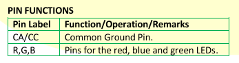
Note that the current limiting resistors for the R and B
lines are 1KΩ while the G line has a 330Ω resistor. This is
not an issue for 5V devices, such as AVR-based