OVERVIEW
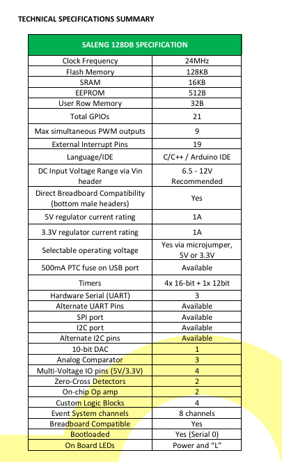
The Saleng 128DB is an Arduino compatible board based on the new
generation AVR128DB microcontroller under the modern AVR®
family. The CPU runs at a maximum of 24MHz. It has a flash memory
size of 128KB, 16KB SRAM, 512B EEPROM and 32B User row. The
microcontroller features four 16-bit timers plus a 12-bit timer, 3
hardware serial ports (UART), 12-bit ADCs or Analog pins, a DAC
capable pin, internal zero cross detectors and op-amps, configurable
custom logic and several other improvements from the “classic”
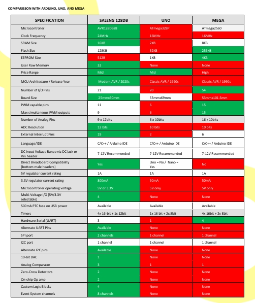
chips such as those used in the Arduino Uno/Nano and Mega.
The Board comes with a total of 21 GPIO’s on board with standard
2.54mm-pitched pin headers. 9 of the 21 pins may be used as analog
input pins (ADC) with one DAC pin. 9 may be used for simultaneous
PWM and all but two GPIOs are external interrupt capable.
Programming may be done via the onboard micro-USB pin. Advance
users may also access the exposed UPDI programming pin at the pin
headers. The board comes with the usual reset button and the
Arduino-Built-In-LED on pin D7.
The Saleng 128DB has a selectable operating voltage of 5V or 3.3V
via the on-board micro jumper. Another jumper is included to allow
user selection of the Multi-Voltage I/O operating voltage (VDDIO2)
between 5V or 3.3V which may act as built-in
level-shifters.
- FEATURES
- AVR128DB28 Microcontroller
- Modern AVR architecture
- CPU Clock Frequency of up to 24MHz
- 16KB of SRAM Size
- 128KB of Flash Size
- 512 Bytes of EEPROM Memory
- Total of 21 GPIO pins
- 11 pins are capable of generating PWM signals
- 9 Analog Pins with 12bit ADC
- Mixed operating voltage of 3.3- and 5-volts via the MVIOs
- Compatible with the Arduino IDE
- Alternate UART and I2C Interface
- Small form factor of 25mmx50mm PCB size
- Power indicator LED, “L” LED
- Affordable price

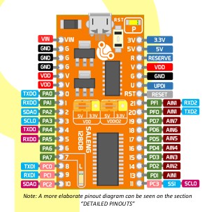
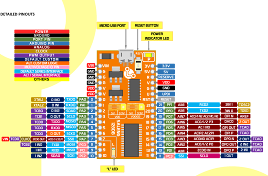
Note: A more elaborate pinout diagram can be seen on the section
“DETAILED PINOUTS”
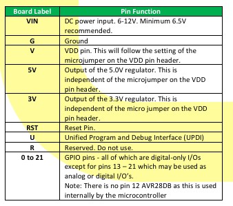
PIN FUNCTION SUMMARY
The table below describes the function of all of the pins on the main
header.
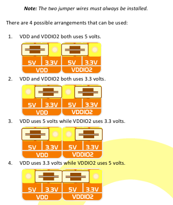
OPERATING VOLTAGE ORIENTATION
The user may change the operating voltage of the Saleng 128DB
board by adjusting the orientation of microjumper at the VDD
header located at the center of the board. This will affect all V pins
and GPIO’s except the 4 MVIO pins whose operating voltage will
depend on the microjumper orientation at the VDDIO2 pins header.
These four pins are as follows:

POWER REQUIREMENTS AND OPTIONS
The board may be powered from the following options.
- MicroUSB port – the board is powered when plugged into
the USB port of a computer or any power supply. Please
ensure you are using a 5V power supply / charger / power
bank. The port is designed for a maximum of 500mA only.
A resettable fuse is installed in this port.

USB DRIVER INSTALLATION
Saleng 128DB requires installation of the CH340 driver which is
widely available for download online. This is required by the
computer to recognize the board as a COM port (in Windows).
Below is a step-by-step guide to install the driver:
- Download the latest version of the driver from the following:
Windows:
https://layadcircuits.com/ds/SalengUno/drivers/CH341SER.ZIP
Mac:
https://layadcircuits.com/ds/SalengUno/drivers/CH341SER_MAC.ZIP
Linux: built-in - Extract the downloaded file with any zip extractor software
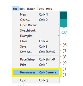
Step 2: After copying the link, Open Arduino IDE. Go to File >
Preferences.
Step 3: Paste the link inside the Box beside “Additional Boards
Manager URLs:” then Click “OK”. Separate with commas if there are
other board links.

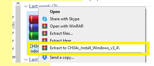
Run the installer.

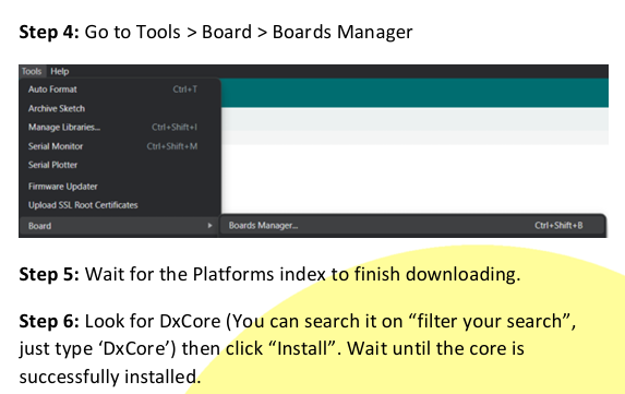
Step 5: Wait for the Platforms index to finish downloading.
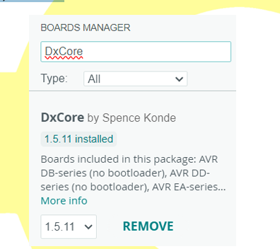
Step 6: Look for DxCore (You can search it on “filter your search”,
just type ‘DxCore’) then click “Install”. Wait until the core is
successfully installed.
- On the window that pops up, click on the Install Button.
- Wait until installation is complete. Note that if you
previously installed the driver, the installation may report a
“failed” installation. If there is a need to reinstall, please
uninstall first then reinstall. - Reboot the computer.
- After reboot, insert the Saleng 128DB into one of the
USB ports of the computer. The computer should now
recognize the board. In Windows, the board will appear as a
COM port under Ports in the Device Manager window.
ADDING THE SALENG 128DBS BOARD IN THE ARDUINO IDE
The Saleng 128DB requires installation of the core files to allow
usage with the Arduino IDE. If interested, the core files are
maintained in this repository:
https://github.com/SpenceKonde/DxCore.
Below is a step-by-step instruction on how to install the board:
Step 1: Copy the Link below or that from the repository:
https://descartes.net/package_drazzy.com_index.json
FIRST UPLOAD / TEST UPLOAD
To confirm successful installation of the core and to test the board,
follow the steps below to upload the “blink” sketch.
Step 1: Go to Tools > Board > DxCore and choose “AVR DB – series
(optiboot)”

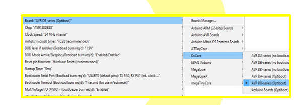
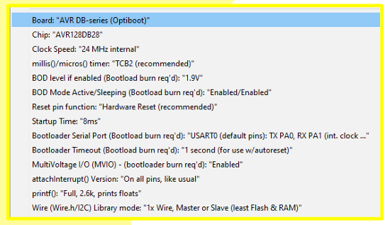
Step 2: Follow the board settings below. The options and
arrangement of these settings may vary in the future but as a
general rule, set the Bootloader Serial Port to “USART0” and the
printf() to “Full…” and keep the rest in default position.
Step 4: Check your Saleng 128DB if its blinking based on the code.
Congratulations! You have successfully programmed your Saleng
128DB.
PERIPHERALS
The following section discusses the different peripherals available in
the Saleng 128DB with emphasis on the hardware/software features
not available in the “classic” boards such as the Arduino
Uno/Nano/Mega.
GENERAL PURPOSE I/Os (GPIOs)
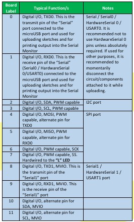
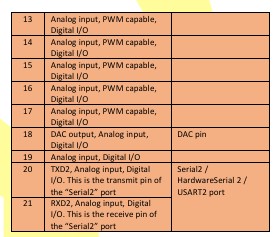
There is a total of 21 GPIOs on the board following the classic
labelling style from “0” to “21”. There is no pin 12. Below is a
summary of the important details. Rows in blue are digital I/Os
capable pins while those in orange are digital and analog capable
I/Os. See also the “Detailed Pinout” section.
Step 3: Check your Port, make sure that your board is connected. Go
to tools > Port > Serial Port and select the port number associated to
your board. Note that the port number is assigned by your
computer’s OS and may change between USB ports.
Note: Install CH340 driver if the port associated with the board does
not appear on the dropdown list under Tools>Ports
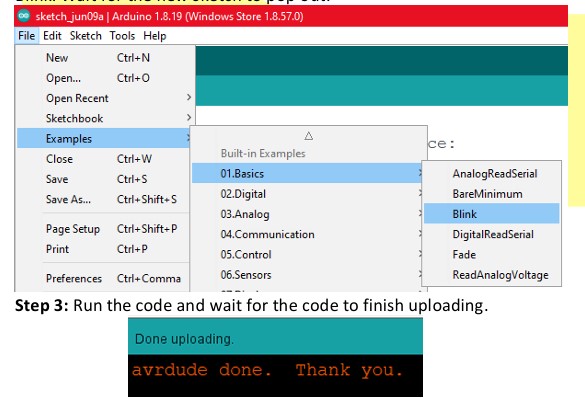
Step 4: After choosing your port, Go to File > Examples > 01. Basics >
Blink. Wait for the new sketch to pop out.

PWM
Refer to the GPIO table for PWM capable pins. The pins 4 & 6, and
pins 5 & 7 are linked, thus, each pair can only output one duty cycle
at a time on one pin or on both pins. Both pairs cannot be used with
the same duty cycle simultaneously.
Timer on Pin 8 is used as the default millis() timer, as a result it loses
its capabilities to output PWM.
Assuming LEDs are connected to the pins defined in the sketch
below, the code will show different brightness levels when
uploaded
int firstLed = 2;
int secondLed = 3;
int thirdLed = 13;
int fourthLed = 14;
int fifthLed = 15;
int sixthLed = 16;
int seventhLed = 17;
void setup()
{
pinMode(firstLed, OUTPUT);
pinMode(secondLed, OUTPUT);
pinMode(thirdLed, OUTPUT);
pinMode(fourthLed, OUTPUT);
pinMode(fifthLed, OUTPUT);
pinMode(sixthLed, OUTPUT);
pinMode(seventhLed, OUTPUT);
}
void loop()
{
analogWrite(firstLed, 127);
analogWrite(secondLed, 255);
analogWrite(thirdLed, 64);
analogWrite(fourthLed, 191);
analogWrite(fifthLed, 127);
analogWrite(sixthLed, 64);
analogWrite(seventhLed, 0);
}
ADC
Saleng 128DB has a default resolution of 10-bits (0-1023) for
compatibility with other boards but the maximum is 12-bits (0
4095). To change the ADC resolution, call the following function:
analogReadResolution(10);//parameter is the resolution: 10/12
The following example shows a 10-bit resolution example program.
This may be helpful when writing code that is compatible with
classic 10-bit Arduino bpards.
void setup()
{
Serial.begin(9600);
//display pin 21's input at default -
//resolution (10 bit)
analogReadResolution (10);
Serial.print ("ADC in 10bits - ");
Serial.println (analogRead(21) );
delay(1000);
}
void loop()
{
}
The sketch mbelow shows the full 12-bit resolution. This is
practically the same as the first sketch except for the resolution
int potpin = 21;
int val = 0;
void setup()
{
Serial.begin(9600));
analogReadResolution(12);
}
void loop()
{
}
val = analogRead(potpin);
Serial.print("ADC in 12bits - ");
Serial.println(val);
delay(1000);ALTERNATE PINS FOR SERIAL INTERFACES
Saleng 128DB have an alternate pin-mapping alternatives that can
be swap with the default pins using the swap() command before
initializing any of the interface( begin() ).


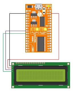
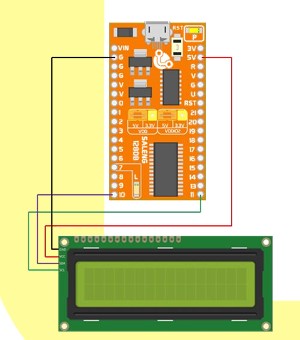
/*For this sketch, we connected an LCD with an
I2C module to with SDA at pin 10 and SCL at
pin 11*/
#include <Wire.h>
#include <LiquidCrystal_I2C.h>
LiquidCrystal_I2C lcd(0x27,20,4);
void setup()
{
Wire.swap(2);//swap default i2c pins to 10 and 11
lcd.init();
lcd.backlight();// initialize the lcd
lcd.setCursor(1,0);
lcd.print("Testing...");
lcd.setCursor(1,0);
lcd.print("Swap command");
}
void loop(){
}
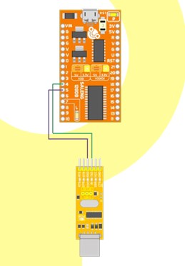
USART (“Serial”) Alternate Interface – Serial0 has alternate pins as
follows:

/*In this code, you must connect pins 4 and 5
to a UART-USB converter and upload code. If code
is successful, the text "Serial Changed" will
appear in the new UART port.
*/
void setup()
{
Serial.swap(1);//swaps pin 0&1 to 4&5
Serial.begin(9600);
Serial.print("Serial Changed");
}
void loop() {
}
Use Serial.swap(0) to change to default pins 0 and 1.
#include <Wire.h>
#include <LiquidCrystal_I2C.h>
LiquidCrystal_I2C lcd(0x27,20,4);
void setup()
{
/* Without Wire.swap() command, the pins
* will automatically set to default: pin 2
(SDA) and pin 3 (SCL)
*/
lcd.init();
lcd.backlight();// initialize the lcd
lcd.setCursor(3,0);
lcd.print("Testing...");
lcd.setCursor(2,1);
lcd.print("Default Pins");
}
void loop(){
}
An example code can be seen here:
/* Opamp.h library is for interfacing with the
built-in AVR-DB Opamp developed in 2021 by
MCUdude
In this code, we used opamp0 as a voltage
follower. Meaning that the output is equal to
the input voltage.
*/

#include <Opamp.h>
void setup()
{
//Connect pin 13 to external input
Opamp0.input_p = in_p::pin;
//Connect N-input to output internally
Opamp0.input_n = in_n::output;
Opamp0.output = out::enable;   //pin 14
Opamp0.init();  // Initialize Opamp0
Opamp::start(); // Start the Opamp hardware
}
void loop() {
}
SPI
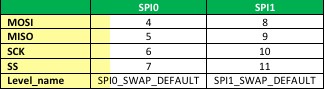
There are two default SPI pins included in the Saleng 128DB board,
their pins are:
For more information concerning OPAMP, please refer to this
website.
Servo Support
The core discussed in this document provides a version of the Servo
library tailored for the Saleng 128DB. You can assess this by going to
Sketch> Include Libraries> Servo_DxCore.h. Please Use this instead
of Servo.h
SPI0 is set as the default pins, but you can interchange them by using
the code SPI.swap(level_name) before SPI.begin().
On-Chip Opamps (OPAMP)
Saleng 128DB have 2 on-chip Opamps.

// Include the necessary libraries
#include <Servo.h>
#include <Servo_DxCore.h>
// Define the servo pin
const int servoPin = 9;
// Create a servo object
#ifdef DXCORE_AVAILABLE
Servo_DxCore servo; // Use Servo_DxCore if
available
#else
Servo servo; // Use default Servo library as
fallback
#endif
void setup() {
// Attach the servo to the pin
servo.attach(servoPin);
}
void loop() {
// Move the servo to 0 and then 180 degrees
servo.write(0);
delay(1500);
servo.write(180);
delay(1500);
}

USEROW
For more information concerning USEROW, please refer to this
website