

DESCRIPTION
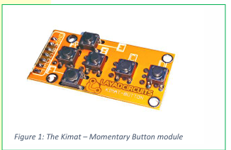
The Momentary Button module is a simple and easy to
use 6 channel push button normally open tactile
switches arranged as a controller pad. Only the 6
buttons are integrated in this compact module allowing
a module size of only 50x25mm board dimension.
Microcontroller users may simply enable the internal
pull-up (or pull down in some microcontrollers) resistors
and avoid the need for external resistors. Arduino /
Saleng-Uno users in particular, may directly insert the
module into the header pins for digital pins 8 – 13 (see
figure 2). The Momentary Button module is part of
Layad Circuits’ Kimat series of rapid prototyping
products.

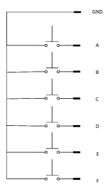
SCHEMATIC
- FEATURES
- 6 Channel Tactile NO push buttons
- Compatible with 3.3V or 5V controllers
- Compact form factor, board dimensions:
- 50x25mm
- Standard 2.54mm pitch headers
- Pin header connects directly with Arduino
- headers
APPLICATION NOTES
APPLICATION NOTES
When the male pin headers are installed at the bottom
side, the module may connect directly, without wires,
with the Arduino / Saleng Uno’s headers 8-13 as show
in figure 2.
PIN FUNCTIONS



Below is an example Arduino sketch demonstrating how
the module may be used. This follows the connection as
shown in figure 2. The sketch simply enables the
internal pull-up resistors and then prints the state of
each pin. As this is a demonstration, it is noteworthy
that certain applications may require debounce code.

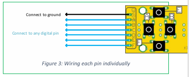
If you need to use other pins, you may simply connect
each pin individually.
const byte KEYA = 13;
const byte KEYB = 12;
const byte KEYC = 11;
const byte KEYD = 10;
const byte KEYE = 9;
const byte KEYF = 8;
byte a,b,c,d,e,f; //stores button states
void setup() {
pinMode(KEYA,INPUT_PULLUP);
pinMode(KEYB,INPUT_PULLUP);
pinMode(KEYC,INPUT_PULLUP);
pinMode(KEYD,INPUT_PULLUP);
pinMode(KEYE,INPUT_PULLUP);
pinMode(KEYF,INPUT_PULLUP);
Serial.begin(9600);
}
void loop() {
a = digitalRead(KEYA);
b = digitalRead(KEYB);
c = digitalRead(KEYC);
d = digitalRead(KEYD);
e = digitalRead(KEYE);
f = digitalRead(KEYF);
if(a == LOW) Serial.print("ON \t");
else Serial.print("OFF \t");
if(b == LOW) Serial.print("ON \t");
else Serial.print("OFF \t");
if(c == LOW) Serial.print("ON \t");
else Serial.print("OFF \t");
if(d == LOW) Serial.print("ON \t");
else Serial.print("OFF \t");
if(e == LOW) Serial.print("ON \t");
else Serial.print("OFF \t");
if(f == LOW) Serial.print("ON \t");
else Serial.print("OFF \t");
Serial.println();
delay(100);
}
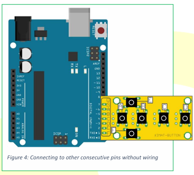
If you are connecting to pins that are consecutive, you
could also use a digital pin as ground by declaring that
pin as output and setting it LOW.
To test, upload the sketch and open the serial monitor
with a baud rate of 9600.


The following Arduino sketch demonstrates how to use
the setup shown in figure 4.
const byte KEYA = 6;
const byte KEYB = 5;
const byte KEYC = 4;
const byte KEYD = 3;
const byte KEYE = 2;
const byte KEYF = 1;
const byte GROUND = 7;
byte a,b,c,d,e,f; //stores button states
void setup() {
pinMode(KEYA,INPUT_PULLUP);
pinMode(KEYB,INPUT_PULLUP);
pinMode(KEYC,INPUT_PULLUP);
pinMode(KEYD,INPUT_PULLUP);
pinMode(KEYE,INPUT_PULLUP);
pinMode(KEYF,INPUT_PULLUP);
pinMode(GROUND,OUTPUT);
digitalWriteGROUND, LOW);
Serial.begin(9600);
}
void loop() {
a = digitalRead(KEYA);
b = digitalRead(KEYB);
c = digitalRead(KEYC);
d = digitalRead(KEYD);
e = digitalRead(KEYE);
f = digitalRead(KEYF);
if(a == LOW) Serial.print("ON \t");
else Serial.print("OFF \t");
if(b == LOW) Serial.print("ON \t");
else Serial.print("OFF \t");
if(c == LOW) Serial.print("ON \t");
else Serial.print("OFF \t");
if(d == LOW) Serial.print("ON \t");
else Serial.print("OFF \t");
if(e == LOW) Serial.print("ON \t");
else Serial.print("OFF \t");
if(f == LOW) Serial.print("ON \t");
else Serial.print("OFF \t");
Serial.println();
delay(100);
}
In case of the Arduino Mega, there are several schemes
to avoid wiring. Figure 5 shows how to wire at either
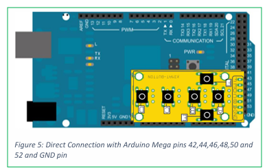
pins 42,44,46,48,50, 52 or pins 43,45,47,49,51, 53 and
the true GND pins beside 52 and 53.

Figure 6 uses pin A0~A5 as inputs and A6 as ground. A6
would have to be set as an output and initialized to the
LOW state.